9 Drawing primitives
We learned about the basics of WebGL programming in the last chapter, but all we could do was clearing the screen and limiting the area to which the clearing affects. To do more complicated things such as displaying a scene, we need to be able to draw primitives. (Recall Section 5.3)
One of the difficulties of learning WebGL is that drawing primitives is intertwined with another aspect of the library: writing GLSL programs. As mentioned Section 7.3.1, we need to create a GLSL program before drawing a primitive. This process has many steps that would take some time to explain. Once it is done, we must also specify the vertices that make up the primitives that we want to draw and connections between them. This process also takes multiple steps as well.
This chapter explains the above two processes. We first plunge ahead through the whole process of creating and using GLSL programs without actually learning how to write them, leaving the details of GLSL programming as the subject of the next chapter. We then learn how to draw triangles. Next, we learn about the index buffer and how it can be used to alternatively specify triangles. We then learn how to draw two other types of primitives: lines and points. Lastly, we learn about viewports and how it can be used to specify the screen area over which primitives are drawn.
9.1 Program 1: Creating and using GLSL programs
The source code of the program is available in the chapter-09/program-01 directory of the source code repoository. Running it, you would see a black canvas and a combo box.
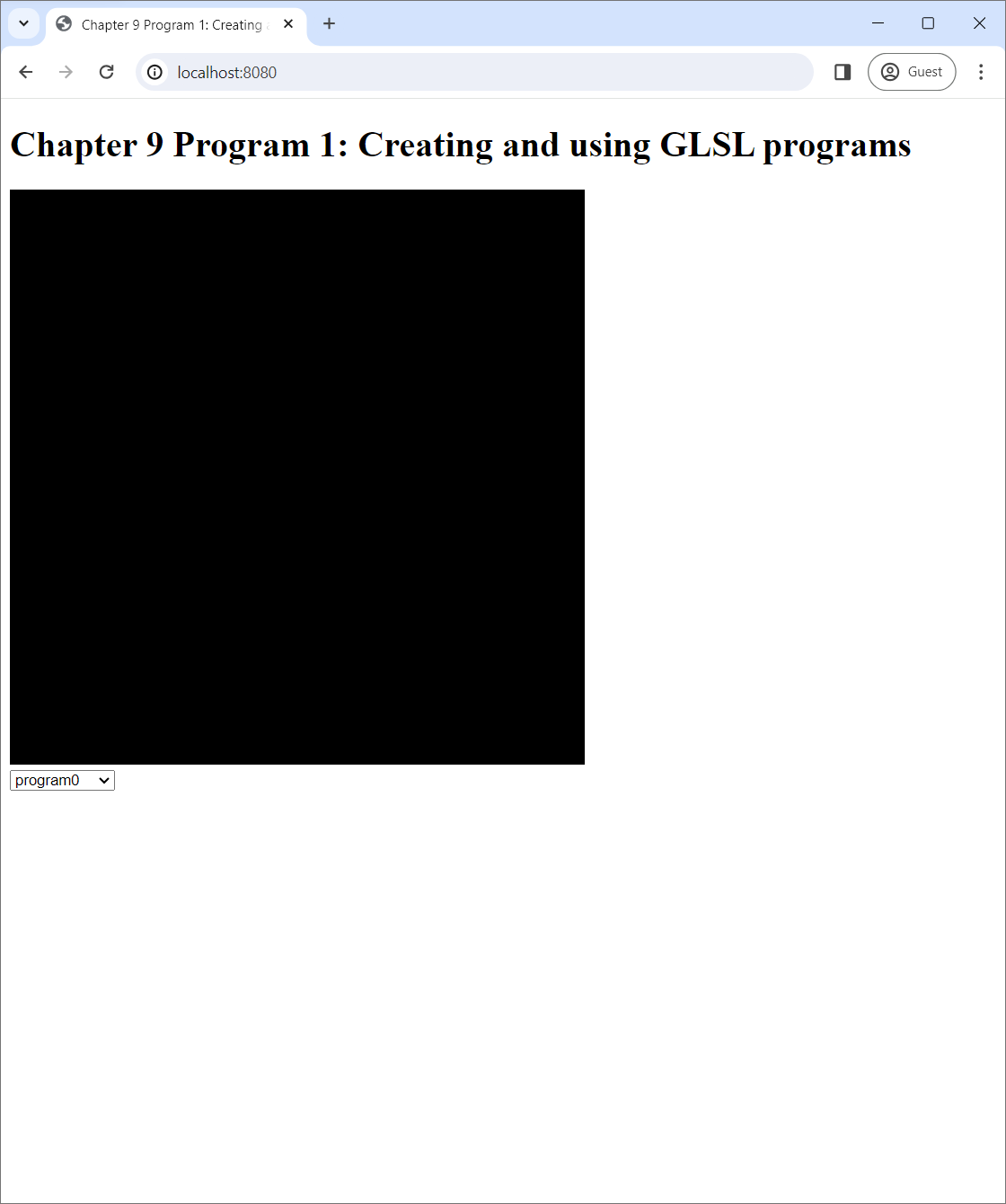
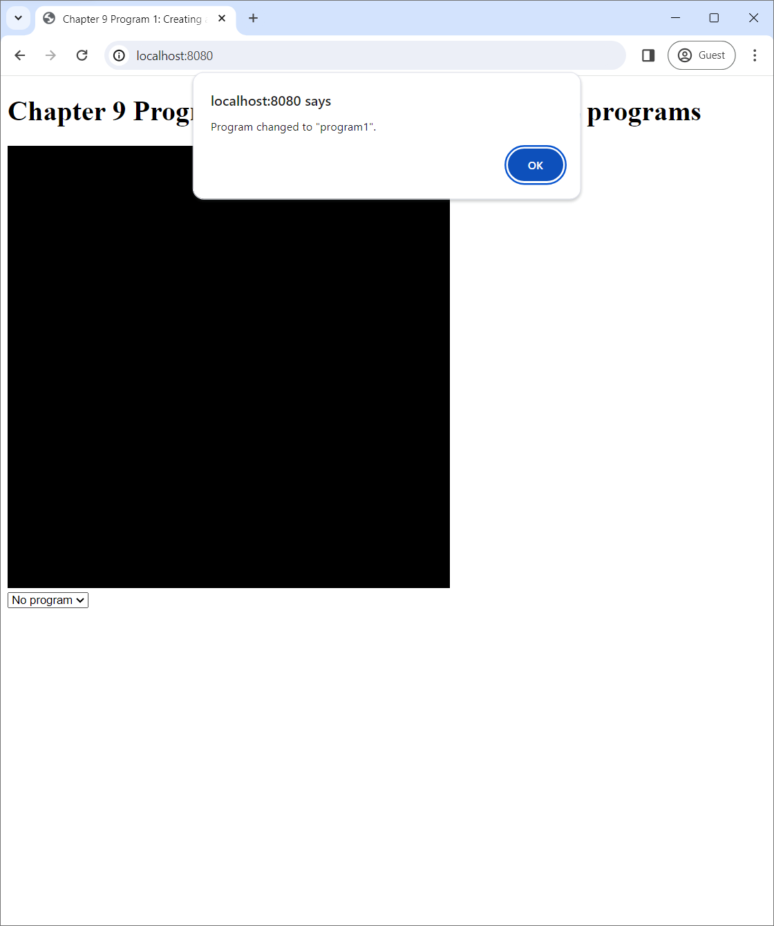
The combo box has three options that you can select: "program0," "program1," and "No program." When you select "program0" or "program1," a dialog box will pop up that tells you that the "program" has changed to the corresponding choice. When you select "No program," the dialog would say the application is not using any program.
 |
 |
 |
| (a) | (b) | (c) |
What happen under the hood is that, at any given time, a WebGL application either "use" a WebGL program or does not use any. Here, when a GLSL program is used, the graphics pipeline is customized according to what is written in the program's code. Our WebGL application starts up, it creates two WebGL programs called "program0" and "program1." It then immediately uses "program0," and it changes the program it uses according to the value of the combo box, which can be changed by the user. However, the application only uses the program, but it does not draw any primitives. So, we cannot see anything on the canvas at all. (We will start putting things on the canvas from Program 2 onward. Please be patient.)
9.1.1 GLSL programs
As previously discussed in Chapter 7, A GLSL program in the context of WebGL 2.0 is made up of two shaders: a vertex shader and a fragment shader. Program 1 has three shaders: a vertex shaders whose source code is in vertex-shader.vert and two fragment shaders whose source code is in fragment-shader-0.frag and fragment-shader-1.frag. The two GLSL programs are created from the shaders as follows:
| GLSL program | Vertex shader | Fragment shader |
|---|---|---|
| program0 | vertex-shader.vert |
fragment-shader-0.frag |
| program1 | vertex-shader.vert |
fragment-shader-1.frag |
9.1.2 The vertex shader
Let us take a brief look at the vertex shader's source code. In this chapter, we would only read it to understand at a high-level what it does without worrying about the syntactic details.
#version 300 es

in vec3 position;

void main() {
    gl_Position = vec4(position, 1);
}vertex-shader.vert.The source code looks syntactically similar to Javascript because it is written in GLSL, a language in the C family to which Javascript also belongs. The first line indicates that we are using GLSL version 3.00 ES, the latest version supported by WebGL 2.0. Similar to system program languages like C and C++, there is a function called main that serves as the "entry point:" it is the function that is run whenever the shader is run.
Recall from Section 7.3.2 that a vertex shader must output clip space coordinates of the vertex being processed. The receiver of this value is the gl_Position variable, which is implicitly defined by the system. Because clip space coordinates have 4 components, the variable is of type vec4, which represents 4-component vectors.
The shader's output is created by taking the value of the position variable and adding the number 1 at the end of it. Now, position is a global variable of type vec3 that is declared with the "in" keyword, signifying that it is an input to the shader. While, in Program 1, we have not put any values in this variable yet, we will put vertex positions in it starting with Program 2.
So, what the vertex shader does is simply copying the $xyz$-coordinates of vertex positions into the clip space coordinates whose $w$-component is always 1. Recall again from Section 7.3.2 that the next step in the graphics pipeline after the vertex shader runs is the perspective divide, in which the NDCs are computed from the clip space coordinates by dividing the clip space $xyz$-coordinates with the $w$-coordinate. Because the $w$-coordinate is always 1, the NDCs would be equal to the vertex positions exactly. The vertex shader thus allows the user of the graphics pipeline to directly specify the NDCs. Because the $x$- and $y$-coordinates of the NDCs represent 2D positions on the canvas, this vertex shader sets up a 2D drawing system. We will see this in more details in other Programs in this chapter.
9.1.3 The fragment shaders
Let us now turn our attention to the fragment shaders. They are even simpler than the vertex one.
#version 300 es

precision highp float;

out vec4 fragColor;

void main() {
    fragColor = vec4(1.0, 1.0, 1.0, 1.0);
}fragment-shader-0.frag.#version 300 es
precision highp float;
out vec4 fragColor;
void main() {
fragColor = vec4(0.0, 1.0, 0.0, 1.0);
}fragment-shader-1.frag.The two source files have the exact same structure. The first lines of both files indicate the GLSL version. Both have main functions, which serve as entry points like in the vertex shader. Both have the precision highp float; lines, which specify the number of bits used to represent values held by the float type. We will study the precise effect of this line later in Chapter 10, so let us not worry about it for now.
We discussed earlier in Section 7.3.2 that a fragment shader must decides whether to discard the fragment it process. If not, it must output the RGBA color of the fragment. The two fragment shaders above always does the latter. The receiver of the output value is the fragColor variable, which is a global variable declared with the keyward out to signify that it is the output. The first fragment shader always output the RGBA color $(1,1,1,1)$, which is white. The second fragment shader always output $(0,1,0,1)$, which is green. In other words, any primitives rendered by the two fragment shaders are white and green, respectively.
As a result, program0, which is created from the vertex shader in Section 9.1.2 and the first fragment shader, would allow the user to directly specify the on-screen position of the vertices, and it would color all primitives white. On the other hand, program1 would do the same thing, but all primitives would be green instead.
9.1.4 How to create a GLSL shader
A GLSL program is made of a vertex shader and a fragment shader. Hence, in order to create a program and render primitive with it, we must create shaders first. The process of creating a shader is encapsulated in the function createShader in the program.js file. The code is reproduced in full below.
function createShader(gl, shaderType, sourceCode) {
  // Step 1: Create the shader.
  let shader = gl.createShader(shaderType);

  // Step 2: Set the shader source.
  gl.shaderSource(shader, sourceCode);

  // Step 3: Compile the shader.
  gl.compileShader(shader);

  // Step 4: Check for errors.
  if (gl.getShaderParameter(shader, gl.COMPILE_STATUS)) {
      return shader;
  }

  // Step 5: Clean up if there are errors.
  let infoLog = gl.getShaderInfoLog(shader);
  gl.deleteShader(shader);
  throw new Error("An error occurred compiling the shader: " + infoLog);
}createShader function.The function has three arguments.
glis the WebGL context we have been creating and using in all programs since the last chapter. We make it a a function argument instead of a global variable like in previous programs because this would allow us to put thecreateShaderfunction in its own file without having to worry about howglis obtained inindex.js.shaderTypeis aGLenumvalue that indicates the type of shader the we would like to create. It can be eithergl.VERTEX_SHADERorgl.FRAGMENT_SHADER.sourceCodeis a string containing the source code of the shader. We will load the source code from the.vertand.fragfiles above, and we will discuss how to do this later.
The process of creating a shader has four steps as indicated by the comments in the code. First, we use the createShader method of the WebGL context to create a WebGLShader object, which is used to represent a shader by the WebGL API. The method accepts a GLenum that indicates the type of the shader to which we just pass the shaderType variable.
let shader = gl.createShader(shaderType);Second, we call the the shaderSource method of the WebGL context to set the source code of the newly created WebGLShader object.
gl.shaderSource(shader, sourceCode);Third, we call the compileShader method of the WebGL context. Here, compiling a shader turns the shader source code, which is human-readable text, into machine code that the GPU can understand and run.
gl.compileShader(shader);Then, we check whether the compilation was successful or not. This is done retrieving the compilation state of the WebGLShader object with the WebGL context's getShaderParameter method, passing gl.COMPILE_STATUS as the second argument. If the compilation is successful, the method would return true. If this is the case, we can return the created WebGLShader object to the function's caller.
if (gl.getShaderParameter(shader, gl.COMPILE_STATUS)) {
  return shader.
}
If compilation fails, we want to inform the function's caller why it fails. This information is available in the shader's "information log," which we can retrived with the WebGL context's getShaderInfoLog method.
let infoLog = gl.getShaderInfoLog(shader);Before we can inform the caller of the infomation log, we clean up the WebGLShader object, which is now cannot be used because of the failed compilation. Here, we delete it with the deleteShader method in order to free resources occupied by the shader so far.
gl.deleteShader(shader);Lastly, we throw a Javascript exception with a message created from the information log.
throw new Error("An error occurred compiling the shader: " + infoLog);Compilation can fail because of various reasons, but the most significant would be syntax errors in the source code. Throwing the above exception is thus very important because it allows us, the programmer, to learn about our mistakes and rewrite the source code to fix them.
9.1.5 How to create a GLSL program
We now turn our attention to the process of creating a GLSL program, which is encapsulated in the createGlslProgram function in program.js. This function creates a GLSL program from two pieces of source code, one for the vertex shader and another for the fragment shader. Its source code is reproduced below.
function createGlslProgram(gl, vertexShaderSource, fragmentShaderSource) {
  // Step 1: Create a program object.
  let program = gl.createProgram();

  // Step 2: Create an attach the shaders.
  let vertexShader = createShader(gl, gl.VERTEX_SHADER, vertexShaderSource);
  gl.attachShader(program, vertexShader);
  let fragmentShader = createShader(gl, gl.FRAGMENT_SHADER, fragmentShaderSource);
  gl.attachShader(program, fragmentShader);

  // Step 3: Link the program.
  gl.linkProgram(program);

  // Step 4: Validate the program.
  gl.validateProgram(program);

  // Step 5: Check for errors.
  if (gl.getProgramParameter(program, gl.LINK_STATUS)) {
      return program;
  }

  // Step 6: Clean up if there are errors.
  let infoLog = gl.getProgramInfoLog(program);
  gl.deleteProgram(program);
  gl.deleteShader(vertexShader);
  gl.deleteShaer(fragmentShader);
  throw new Error("An error occurred linking the program: " + infoLog);
}createGlslProgram function.The return value of this function is an instance of the WebGLProgram object, which we create in Line 3 with the createProgram method of the WebGL context.
let program = gl.createProgram();After creating an instance, we need to specify a vertex shader and a fragment shader that are going to be used to make the program. This can be done with the attachShader method of the WebGL context. In Listing 9.5, we obtain the shaders by calling the createShader function with the appropriate arguments.
let vertexShader = createShader(gl, gl.VERTEX_SHADER, vertexShaderSource);
gl.attachShader(program, vertexShader);
let fragmentShader = createShader(gl, gl.FRAGMENT_SHADER, fragmentShaderSource);
gl.attachShader(program, fragmentShader);
After the we have specified the shaders, we can "link" the program with the linkProgram. Here, "linking" means combining the shaders to create a complete GLSL program.
gl.linkProgram(program);If linking is successful, the creation process is complete, and we can start using the program immediately. However, like compiling a shader, linking can fail due to coding errors. It is good practice to check for them and report any problems to the user. To do so, we first call the validateProgram of the WebGL context on the created program.
gl.validateProgram(program);The next step would be to call the getProgramParameter method on the program to get its link status: gl.getProgramParameter(program, gl.LINK_STATUS). The return value is a boolean which is true if and only if linking was successful. If this is the case, we can return the created program and exit the function.
if (gl.getProgramParameter(program, gl.LINK_STATUS)) {
  return program;
}
Note that the process to check for linking errors is a little more complicated than that to check for shader compiling errors. In Section 9.1.4, we can call getShaderParameter immediately after callling compileShader. However, in this section, we must call validProgram between tthe calls to linkProgram and getProgramParameter.
Otherwise, we know that linking failed, and we need to fetch the error message and clean up the unused programs can shaders. Similar to what we did when compiling a shader, we can retrieve the error message with WebGL context's getProgramInfoLog method.
let infoLog = gl.getProgramInfoLog(program);Deleting a program can then be done with the deleteProgram method of the WebGL context. However, it is not enough to just delete the program here. We must also delete the shaders that we created earlier too.
gl.deleteProgram(program);
gl.deleteShader(vertexShader);
gl.deleteShaer(fragmentShader);
Lastly, we throw an exception with the retrieved error message.
throw new Error("An error occurred linking the program: " + infoLog);9.1.6 Loading Source Code and Creating Programs from It
In the last section, we just discussed how to create a GLSL program if we have access to shader source code which is stored in Javascript strings. Now, we must figure out how get a hold of these strings.
Recall from Section 9.1.2 and Section 9.1.3 that the source code is stored in three separte files: vertex-shader.vert, fragment-shader-0.frag, and fragment-shader-1.frag. When our WebGL program is served by a web server, these files will be available in the same directory as index.html. As a result, we need to read the files' contents and return them as strings. This is done with the loadText function in the index.js file, which uses the Fetch API to do the job.
async function loadText(url) {
  let fetchResult = await fetch(url);
  return fetchResult.text();
}
The two GLSL programs are created in the createPrograms function (not to be confused with the createGlslProgram function in the last section), whose code is reproduced in full below.
async function createPrograms(gl) {
  let vertexShaderSource = await loadText("vertex-shader.vert");
  let fragmentShader0Source = await loadText("fragment-shader-0.frag");
  let fragmentShader1Source = await loadText("fragment-shader-1.frag");

  let program0 = createGlslProgram(gl, vertexShaderSource, fragmentShader0Source);
  program0.name = "program0";

  let program1 = createGlslProgram(gl, vertexShaderSource, fragmentShader1Source);
  program1.name = "program1";

  return [program0, program1];
}
We see that we use the loadText function to retrieve the source code from the three files. Then, we use createGlslProgram to create two programs with the pairs of source code we discussed earlier in Section 9.1.1. The following two lines
    :
  program0.name = "program0";

    :
  program1.name = "program1";
just add a field called name to the program objects so that we can use these names to identify the programs later. They are specific of the functionality of Program 1 and are not in any way a standard practice in WebGL programming. The function ends by returning the two programs inside a 2-element array.
9.1.7 Using a Program
At any given time in the life of a WebGL application, there is at most one GLSL program that is being "used." When a program is used, its shaders are used to modified the relevant steps in the graphics pipeline, allowing for custom vertex and fragment processing. For example, all rendered primitives would be white and green when "program0" and "program1" are used, respectively.
We can tell WebGL to start using a specific program with the useProgram method of the WebGL context. The method takes one argument, a WebGLProgram object to use.
gl.useProgram(<program-object-to-use>);We can also tell WebGL to not use any program (and therefore we would not be able to render any primtiives) by supplying null as the argument.
gl.useProgram(null);The GLSL program being used by WebGL is referred to as the "current program." It can be retrieved by getting the CURRENT_PROGRAM parameter of the WebGL context.
gl.getParameter(gl.CURRENT_PROGRAM)9.1.8 The Rest of Program 1
We have gone through everything about how to create GLSL programs and how to use them. In this section, we go through the rest of the code in index.js and discuss how the whole program works.
We start with the bottommost section of the file, which creates the WebGL context and sets up the drawing loop.
let lastProgram = null;

:
:
:

let canvas = $("#webglCanvas");

let gl = canvas[0].getContext("webgl2");
if (!gl) {
    alert("Cannot get WebGL 2 context!");
} else {
    createPrograms(gl).then(programs => {
        gl.useProgram(programs[0]);
        lastProgram = programs[0];
        window.requestAnimationFrame(() => updateWebGL(gl, programs));
    });
}
First, we declare a variable called lastProgram to store the last program being used. This variable is only used for accounting as it allows the program to show an alert when the user changes the GLSL program. We will not need this variable again in next example programs.
After successfully retrieving the WebGL context, we call createPrograms to create the two programs, which are returned in a 2-element array. We process the programs with a callback function given as the argument of the then method. The callback function immediately uses program0 and assigns it to the lastProgram variable. We then start the drawing loop by requesting the browser to run the updateWebGL function when the screen refreshes. The code of the function is reproduced in full below:
function updateWebGL(gl, programs) {
  gl.clearColor(0.0, 0.0, 0.0, 0.0);
  gl.clear(gl.COLOR_BUFFER_BIT);

  // Use the program.
  let programName = $("#programName").val();
  if (programName == "program0") {
      gl.useProgram(programs[0]);
  } else if (programName == "program1") {
      gl.useProgram(programs[1]);
  } else {
      gl.useProgram(null)
  }
  reportCurrentProgram(gl);

  window.requestAnimationFrame(() => updateWebGL(gl, programs));
}
The function sets the clear color to black and clears the screen, and this makes the canvas always black. The line let programName = $("#programName").val(); retrieves the choice the use makes with the combox box in the web page with the help of JQuery. Next, the if statement uses the program specified by the user. Then, the reportCurrentProgram function shows the appropriate alert when the program changes. The last statement continues the loop by requesting the updateWebGL function to be called again.
Let us now look at the last unexplained piece, the reportCurrentProgram function.
function reportCurrentProgram(gl) {
  // Get the program being used.
  let currentProgram = gl.getParameter(gl.CURRENT_PROGRAM);
  if (currentProgram != lastProgram) {
      if (!currentProgram) {
          alert("Currently not using any program.");
      } else {
          alert("Program changed to \"" + currentProgram.name + "\".");
      }

  }
  lastProgram = currentProgram;
}
We can see from the source code that the function retrieves the current program and checks whether it is the same as the lastProgram. If not, it shows an alert. Notice that it deals with the case where lastProgram is null (i.e., when no program is being used) differently. Lastly, it sets the lastProgram to the current program so that it correctly shows the right alert again when reportCurrentProgram is called.
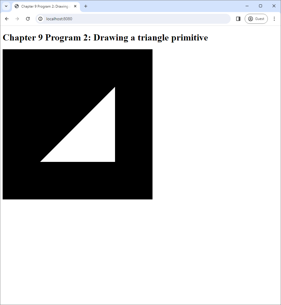
9.2 Program 2: Drawing a triangle primitive
Now that we know how to create and use GLSL programs, we are ready to draw primitives. Program 2 demonstrates how to draw a triangle primitive in the simplest possible way.
Like creating a GLSL program, the process of drawing primitives also have multiple steps. The steps can be broken into two parts.
- Defining a buffer that hold vertex data. One can also optionally define another buffer that holds indices as well.
- Drawing the primitives using the defined buffers.
9.2.1 The buffers
Recall from Chapter 5 primtives are made of vertices, and each vertex has associated data such as its position, color, and normal. Because WebGL draws primitives using the GPU, we must download the vertice's data to the GPU first. This requires us to allocate a piece of GPU memory, which we shall call the vertex buffer, to store this data. Then, we must transfer the data to the GPU.
Recall also that defining primitives requires information about connections between the vertices, and this information can be stored in an index buffer. Note that the index buffer in Chapter 5 is a Javascript array. However, if we want WebGL to use it, we must store the data that it holds in a buffer that resides in the GPU too. For simplicity, we shall refer to the piece of GPU memory that hold index data as an index buffer as well.
Rendering primitives always require a vertex buffer, but an index buffer is optional. This is because WebGL allows connections between vertices to be defined implicitly as follows. If we want to draw 10 triangle primitives, we can create a vertex buffer that holds data for 30 different vertices. WebGL will then treat three consecutive vertices in this buffer as a traingle. This is the way of specifying connections that is used in Program 2, but we will use an index buffer to define connections explicity in Program 3.
9.2.2 Creating a vertex buffer
The following lines of code in Program 2's index.js creates a vertex buffer.
let vertexData = new Float32Array([
  -0.5, -0.5, 0.0,
  0.5, -0.5, 0.0,
  0.5, 0.5, 0.0
]);
let vertexBuffer = createVertexBuffer(gl, vertexData);
First, we create a Javascript typed array to hold the vertex data. WebGL requires that data that are going to be transferred to a GPU buffer be stored in one of 4 different Javascript data types. In this book, we will use typed arrays because it is convenient and simple. Here, we use a typed array where each element is a 32-bit floating point number. The array has 9 elements, which can be divided into 3 different groups. Each group corresponds to a vertex and contains its $x$-, $y$- and $z$-coordinates. Because there are 3 vertices, we can draw exactly 1 triangle with this vertex buffer.
Next, we pass the vertexData array to the createVertexBuffer function, whose code resides in another file: vertex-buffer.js. We reproduce the function in full below.
function createVertexBuffer(gl, vertexData) {
  // Step 1: Create a buffer object.
  let vertexBuffer = gl.createBuffer();

  // Step 2: Bind the buffer to the ARRAY_BUFFER target.
  gl.bindBuffer(gl.ARRAY_BUFFER, vertexBuffer);

  // Step 3: Transfer the vertex data to GPU.
  gl.bufferData(gl.ARRAY_BUFFER, vertexData, gl.STATIC_DRAW);

  // Step 4: Unbind the buffer.
  gl.bindBuffer(gl.ARRAY_BUFFER, null);

  // Step 5: Return the vertex buffer.
  return vertexBuffer;
}createVertexBuffer function of Program 2.The first step is to use the WebGL context's createBuffer method to create a WebGLBuffer object, which WebGL uses to represent a buffer in GPU memory.
The second step is to "bind" the created buffer with the bindBuffer method. Here, "binding" means telling WebGL to "use" the specified buffer for the next buffer-related operations until the user specifies otherwise, much like using a GLSL program. However, while at most one program can be used at a time, multiple buffers can be bound simultaneously because WebGL keeps tracks of multiple buffers, each used for a different purpose. One can think of this as having multiple buffer "slots," where a slot corresponds to a purpose. Binding means filling the slot with a buffer that the user specifies. Confusingly, the library calls such a slot a "target." In this chapter, we will be using two targets that are indicated by the following GLEnum values:
gl.ARRAY_BUFFER: The target for a buffer that stores vertex attributes.gl.ELEMENT_ARRAY_BUFFER: The target for a buffer that stores indices (i.e., the index buffer).
The bindBuffer method has two arguments. The first is the GLEnum that indicates the target. The second is the buffer to bind to the target. In the code above, we immediately bind the created buffer to the gl.ARRAY_BUFFER target, indicating that we will use this buffer to store vertex attributes until we change our mind. The gl.ELEMENT_ARRAY_BUFFER target is not used in Program 2, but we will use it in Program 3.
The third step is to download the vertex data given in the vertexData variable to the GPU. This is done with the bufferData method. The first argument to the method is a GLEnum which indicates the target buffer where the data are to be downloaded to. The second is the Javascript variable that holds the data. The third is another GLEnum that indicates the usage pattern of the data in the buffer, and WebGL will use this information to optimize how the data are stored. Here, the third argument is gl.STATIC_DRAW, which indicates that the data in the buffer is specified once and will not change. Moreover, it will be used multiple times by the application. The GLEnum is a perfect fit for what we want to do in Program 2 because the training we draw does not change, and we draw it once every frame.
The fourth step is to "unbind" the buffer, which simply means to free the target the buffer is occupying after we are done with it. This can be done by calling bindBuffer with null as the buffer to be bound. This step is optional because the bound buffer would change once we call bindBuffer with a diferent buffer object. However, we include this step for hygienic purpose: we assume that the gl.ARRAY_BUFFER target is not bound to anything before createVertexBuffer is called, and we want to leave the target in the same state when the function returns.
Lastly, we return the created buffer as the return value of the function.
9.2.3 Drawing primitives
Naturally, the code that draws primitives must be invoked every time we update the screen, so it belongs inside the updateWebGL function. However, before delving into the details of the function, let us see first how the function is used in the overall program. This can be seen in the lines of code below.
let vertexData = new Float32Array([
    -0.5, -0.5, 0.0,
    0.5, -0.5, 0.0,
    0.5, 0.5, 0.0
]);
let vertexBuffer = createVertexBuffer(gl, vertexData);

createProgram(gl).then(program => {
    windows.requestAnimationFrame(() => updateWebGL(gl, program, vertexBuffer));
});
We note earlier that drawing a primitive requires a GLSL program, so we must create one before anything can be drawn. In the above code, this is done with the createProgram function, which is almost the same as the createPrograms function of Program 1, except that it only creates and returns one program. The vertex shader's source is in vertex-shader.vert, which is a copy of the same file in Program 1. The fragment shader's source is in fragment-shader.frag, which is a copy of Program 1's fragment-shader-0.frag. As explained earlier, the GLSL program made of these two shaders would allow its user to directly specify the screen positions of the vertices, and all rendered primitives would be white.
In addition to a GLSL program, we also need a buffer containing vertex data, and we will use the vertex buffer whose creation as described in the last section. As a result, Program 2's updateWebGL function takes 3 arguments: the WebGL context, a program, and a vertex buffer. Let us now looks at its source code.
function updateWebGL(gl, program, vertexBuffer) {
  gl.clearColor(0.0, 0.0, 0.0, 0.0);
  gl.clear(gl.COLOR_BUFFER_BIT);

  // *******************************
  // * Drawing triangle primitives *
  // *******************************
  // Step 1: Use the program.
  gl.useProgram(program);
  // Step 2: Get location of the attribute we want to assign with the data from the vertex buffer.
  let positionLocation = gl.getAttribLocation(program, "position");
  // Step 3: Enable the attribute.
  gl.enableVertexAttribArray(positionLocation);
  // Step 4: Bind the buffer we want to use.
  gl.bindBuffer(gl.ARRAY_BUFFER, vertexBuffer);
  // Step 5: Assign the attribute to the bound buffer.
  gl.vertexAttribPointer(positionLocation, 3, gl.FLOAT, false, 3 * 4, 0);
  // Step 6: Unbind the buffer.
  gl.bindBuffer(gl.ARRAY_BUFFER, null);
  // Step 7: Draw.
  gl.drawArrays(gl.TRIANGLES, 0, 3);
  // Step 8: Unuse the program.
  gl.useProgram(null);

  window.requestAnimationFrame(() => updateWebGL(gl, program, vertexBuffer));
}updateWebGL function of Program 2.As usual, the function starts with clearing the screen and ends with requesting that itself be run again when the screen updates the next time. The main difference between this function and those of other programs is the multi-step process to render a primitive.
Before rendering a primitive, we must make sure that the GLSL program that processes the vertices and the fragments is used by WebGL. So, Step 1 of the process is using a program, and this is paired with Step 8, which unuses it.
Next, we need to specify how the program would access the vertex data that we have prepared. More simply, we need to tell WebGL which variables in the programs are going to get what portion of the vertex data. This specification is done in Step 2 to Step 6. These 5 steps can be divided into two stages.
- The first stage consists of Step 2 and Step 3. In this stage, we identify the variables that are to receive vertex data and "enable" them.
- The second stage consists steps from Step 4 to Step 6. We specify the portion of the vertex buffer that are going to be stored into the variables we selected.
9.2.3.1 Identifying and enabling attribute variables
There are a number of special types of variables in WebGL. One type of these special variables is called attribute variables. These are global variables in a vertex shader that are marked with the keyword in. These variables are called "attribute" variables because they are mainly used to store vertex attributes. The vertex shader of Program 2 has one attribute variable called position, and it was declared as follows:
in vec3 position;We see that the variable has type vec3, which means that the variable is used to store 3-component vectors. The variable name implies that these 3-vectors are 3D positions of the vertices.
When WebGL compiles a vertex shader, it assigns a unique integer called a location to each attribute variable. This number can be used later in Javascript code to refer to particular variables that we are interested in. In our case, we need to know the location of the position variable because we want to connect it to the vertex buffer. The location of an attribue variable can be retrieved using the getAttribLocation method of the WebGL context. The method is used in the source code of Program 2 as follows:
// Step 2: Get location of the attribute we want to assign with the data from the vertex buffer.
let positionLocation = gl.getAttribLocation(program, "position");
As we can see, the method takes two arguments. The first is the program, and the second is a string whose content is the name of the variable. Because the location will be used multiple times later, we store it in the variable positionLocation for convenience.
All attribute variables in a vertex shader are "disabled" by default. A disabled variable cannot be used inside a vertex shader because we cannot tell what values the variable would take when the vertex shader is executed. Thus, after an attribute variable's location, we should "enable" the variable immediately. This can be done with the enableVertexAttribArray method of the WebGL context as follows:
// Step 3: Enable the attribute.
gl.enableVertexAttribArray(positionLocation);
9.2.3.2 Specifying vertex attribute data
After identifying and enabling the attribute variable we would like to use, we need to specify what data these variables would receive. More comcretely, we have a number of vertex buffers that store vertex data, and we must let WebGL know which part of which vertex buffer would be streamed to which attribute variable.
Before we can do the above, we need to bind a vertex buffer that the attribute variable would take data from. This is done in Step 4 of Listing 9.7, and we use the same gl.bindBuffer method as in Section 9.2.2. Step 4 is paired with Step 6 where we unbind the buffer for programming hygiene.
The most complicated step in this stage is Step 5 where we use the vertexAttribPointer method of the WebGL context to connect the vertex data to the attribute variable.
// Step 5: Assign the attribute to the bound buffer.
gl.vertexAttribPointer(positionLocation, 3, gl.FLOAT, false, 3 * 4, 0);
The method has 6 parameters.
The first parameter is the location of the variable we would like to use. In our case, this is the location of the position attribute variable that we have saved in the positionLocation variable.
The second parameter is the number of components of the attribute variable. Because the position attribute variable is a vec3, it represents a vector with 3 components. So, the value of the parameter is naturally 3. By the same logic, the parameter would be 2 if the atttribute variable has type vec2 and 4 if the attribute variable has type vec4. We will learn more about these GLSL types in the next chapter.
The third parameter is the GLenum which represents the type of the elements of the vertex buffer. Because we prepared our vertex buffer with a Float32Array, the parameter value would be gl.FLOAT. (In fact, the value would be gl.FLOAT most of the times in the rest of the book.) On the other hand, if we created the vertex buffer with an Int32Array, the parameter value would be gl.INT.
The fourth parameter is a boolean value. If true, WebGL would "normalize" the data before storing it into the attribute variable. This normalization only happends when the attribute variable store floating point values, but the vertex buffer stores integer values. (Note: This is not the same as vector normalization in Section 3.5.1.) The parameter has not effect otherwise. Because each component of vec3 stores a floating point number and our buffer also stores floating point numbers, the parameter has no effect. We arbitrarily leave it as false. (In fact, we will set this variable to false for the rest of this book.)
The fifth parameter is an integer called the stride. It is the distance in bytes between one instance of the vertex attribute value and the next instance in the vertex buffer. The best way to think about this to think of the vertex buffer as an interleaved buffer (Section 5.2). An interleaved buffer is divided into contiguous blocks where each block stores multiple attributes of a vertex, and each block has the same size in bytes. The stride here would be the size of each such block. In our case, we set the parameter value to 3*4, which is equal to 12. This is because, for our vertex buffer, each vertex has only one parameter: the position. A position is a vector with 3 components, and each component is stored as a floating-point number in the vertex buffer. As a floating-point number is 4 bytes in size, each block in the vertex buffer has $3 \times 4 = 12$ bytes.
The sixth parameter is another integer, and it is called the offset. It is the number of bytes from the start of the interleaved buffer block to the start of the data of the vertex attribute in question. In our case, the offset is 0 because our attribution, the position, is already at the start of the block. The offset will be non-zero for attributes that are not the first one in the interleaved buffer, and we will see this in the next chapters. A good sanity check for the value of the offset is that it must be at least 0 and must also be less than the stride.
Once we have specified the data that will fill the attribute variable, we can unbind the vertex buffer like in Step 6 of the code.
9.2.3.3 Drawing
Step 7 draws the primitive with the drawArrays method of the WebGL context.
// Step 7: Draw.
gl.drawArrays(gl.TRIANGLES, 0, 3);
The arguments to the method, expecially the the numbers 0 and 3, are rather cryptic. So let's look at them one by one.
The first parameter is the GLEnum that indicates the primitive type we want to draw. You can see all the possible values by looking at the table in Section 5.3. Because we want to draw a triangle, we specify gl.TRIANGLEs.
The second parameter is called first. It is the zero-based index of the first vertex in the vertex buffer that we wish to use to draw the primitive(s). The third parameter is called count, and it is the number of vertices from that indexed by first that we want to use in drawing. Hence, drawArrays tells WebGL to use a contiguous chuck of the vertex buffer to draw the primitives specified in the first argument.
In our case, our vertex buffer has only 3 vertices, which can make exactly one triangle. We thus set first to 0, which is the index of the first vertex, and count to 3, which is the number of all vertices. If the vertex buffer stores more than one triangle primitives, we can choose draw any set of consecutive triangles in the buffer by setting these two variables appropriately.
It is important to note that count must be consistent with the type of primitive to be drawn. When we draw triangles, count should be divisible by 3. When we draw line segments, count should be divisible by 2. For points, count can be any non-negative number.
We have gone through a lot of steps in order to just draw a single triangle. This shows us that 3D rendering requires much preparation. As a recap, let us list what are required before we call drawArrays.
- We must have prepared a GLSL program and used it.
- We must locate all the attribute variables in the GLSL program and enable them.
- We must have prepared a vertex buffer and connect it to the attribute variables in the GLSL program.
Again, after we are done with drawing primitives, we should clean up by unusing the program, and this is done in Step 8.
9.3 Program 3: Drawing triangle primitives using an index buffer
Program 2 draws a triangle primitive using only a vertex buffer. As mentioned in Section 9.2.1, connection between vertices is defined explicitly: we must prepare the buffer so that each three consecutive vertices in it contain vertex positions of triangles. This can be wasteful when multiple triangles share the same vertices because the data of those vertices must be repeated multiple times.
The wastefulness program can be mitigated by using an index buffer, which stores indices of vertices in the vertex buffer in the order that from primitives. This representation is much more economical because (1) we can store vertex data with no redundancy, and (2) when a vertex is used multiple times, we only need to repeat its index instead of all vertex's data.
WebGL supports representing meshes with index buffers, and Program 3 uses one to draw a mesh containing two triangles that share vertices with each other. Below is a screenshot of the program, which shows a white square.

9.3.1 Creating an index buffer
Program 3's source code is mostly the same as that of Program 2. One of the main difference is that Program 3 has one more file called index-buffer.js. It contains a function called createIndexBuffer, which, as the name implies, is used to create an index buffer to represent a mesh. Again, before we take a look at the function, we shall see how it is used in the main program.
// **************************
// * Creating vertex buffer *
// **************************
let vertexData = new Float32Array([
    -0.5, -0.5, 0.0,
    0.5, -0.5, 0.0,
    0.5, 0.5, 0.0,
    -0.5, 0.5, 0.0
]);
let vertexBuffer = createVertexBuffer(gl, vertexData);

// *************************
// * Creating index buffer *
// *************************
let indexData = new Int32Array([
    0, 1, 2,
    0, 2, 3
]);
let indexBuffer = createIndexBuffer(gl, indexData);

createProgram(gl).then(program => updateWebGL(
  gl, program, vertexBuffer, indexBuffer));
Like in Program 2, we first create a vertex buffer to store vertex data. This time, though, our vertex buffer has 12 elements instead of 9 because now we want to draw a square, which has 4 vertices.
The main difference between Program 2 and Program 3 is the creation of the index buffer. Similar to a vertex buffer, we can store the data that are going to be stored in an index buffer can be stored in 4 Javascript, and we have chosen to use a typed array. However, we use Int32Array instead of a Float32Array because each element of an inde buffer is an integer, not a floating point number like vertex coordinates.
The type array that contains the index data has 6 elements because we will draw a square that is made up of 2 triangles. The first triangle is made of vertices whose indices are 0, 1, and 2, and they form a right triangle whose right angle is the bottom left corner of the square. The second triangle's indices are 0, 2, and 3, and it is a right triangle whose right angle is the top left corner of the square. Notice that the indices are ordered so that the vertices swirl in the counterclockwise direction, following the convention that a counterclockwise swirl signifies the front face (Section 6.2).
Now, let us look at the createIndexBuffer function in the index-buffer.js file.
function createIndexBuffer(gl, indexData) {
  // Step 1: Create a buffer object.
  let indexBuffer = gl.createBuffer();

  // Step 2: Bind the buffer to the ELEMENT_ARRAY_BUFFER target.
  gl.bindBuffer(gl.ELEMENT_ARRAY_BUFFER, indexBuffer);

  // Step 3: Transfer the buffer data.
  gl.bufferData(gl.ELEMENT_ARRAY_BUFFER, indexData, gl.STATIC_DRAW);

  // Step 4: Unbind the buffer.
  gl.bindBuffer(gl.ELEMENT_ARRAY_BUFFER, null);

  // Step 5: Return the buffer.
  return indexBuffer;
}
We see that the createIndexBuffer function is very similar to the createIndexBuffer function. It has the same number of steps, and the steps use exactly the same methods of the WebGL context. The only difference is that the GLEnum that is used with the glBindBuffer and glBufferData methods are now gl.ELEMENT_ARRAY_BUFFER instead of gl.ARRAY_BUFFER.
9.3.2 Using the index buffer
The index buffer created above is used in the updateWebGL function. Its source code is reproduced below.
function updateWebGL(gl, program, vertexBuffer, indexBuffer) {
  gl.clearColor(0.0, 0.0, 0.0, 0.0);
  gl.clear(gl.COLOR_BUFFER_BIT);

  // *****************************************************
  // * Drawing triangle primitives using an index buffer *
  // *****************************************************
  // Step 1: Use the program.
  gl.useProgram(program);
  // Step 2: Get location of the attribute we want to assign with the data from the vertex buffer.
  let positionLocation = gl.getAttribLocation(program, "position");
  // Step 3: Enable the attribute.
  gl.enableVertexAttribArray(positionLocation);
  // Step 4: Bind the buffer we want to use.
  gl.bindBuffer(gl.ARRAY_BUFFER, vertexBuffer);
  // Step 5: Assign the attribute to the bound buffer.
  gl.vertexAttribPointer(positionLocation, 3, gl.FLOAT, false, 3 * 4, 0);
  // Step 6: Unbind the buffer.
  gl.bindBuffer(gl.ARRAY_BUFFER, null);
  // Step 7: Bind the index buffer.
  gl.bindBuffer(gl.ELEMENT_ARRAY_BUFFER, indexBuffer);
  // Step 8: Draw with drawElements.
  gl.drawElements(gl.TRIANGLES, 6, gl.UNSIGNED_INT, 0);
  // Step 9: Unbind the indexbuffer.
  gl.bindBuffer(gl.ELEMENT_ARRAY_BUFFER, null);
  // Step 10: Unuse the program.
  gl.useProgram(null);

  window.requestAnimationFrame(() => updateWebGL(gl, program, vertexBuffer, indexBuffer));
}
The function is a little more that that of the Program 2. It has an extra parameter, indexBuffer. It also has a few more steps, but the structure is mostly the same. We first need to use the GLSL program in Step 1 and then unuse it in the last step. (The GLSL program being used here is exactly the same as the one in Program 2.) Once we use the program, we find the location of the attribute variable that will receive the vertex position data in Step 2 and enable it in Step 3. We then specify the data that will go into the attribute variable in Step 5, 6, and 7 in the exact manner discussed in Section 9.2.3.
However, drawing is now done differently. In Program 2, this is accomplicated by one call to the drawArrays method, but now we use three statements. In the first statement, we bind the index buffer to the gl.ELEMENT_ARRAY_BUFFER slot, indicating that we will be using the index buffer.
// Step 7: Bind the index buffer.
gl.bindBuffer(gl.ELEMENT_ARRAY_BUFFER, indexBuffer);drawElements as follows.
// Step 8: Draw with drawElements.
gl.drawElements(gl.TRIANGLES, 6, gl.UNSIGNED_INT, 0);
The method is simpler than drawArrays because it has fewer arguments.
- The first argument is the type of primitive we want to draw, which is
gl.TRIANGLESin our case. - The second argument is the number of indices in the index buffer that we would like to use. Because we want to use every index in it, we set the argument to 6.
- The third argument is the data type of each index in the index buffer. Its value can either be
gl.UNSIGNED_BYTE,gl.UNSIGNED_SHORT, andgl.UNSIGNED_INT. They indicate that an index takes 1 byte, 2 bytes, and 4 bytes, respectively. In our case, we created our index buffer with anInt32Arraywhere each element has 4 bytes, so we have to usegl.UNSIGNED_INT. - The last argument is called
offset, and it is the index of the first index in the buffer that we would like to use. We set the value to 0, indicating that we want to start from the very first index.
For the rest of the book, we will be drawing primitives using both the vertex buffer and the index buffer instead of just using the vertex buffer alone. Let us review what is required to draw primitives with an index buffer with drawElements before we move on to the next section.
- We must have prepared a GLSL program and used it.
- We must locate all the attribute variables in the GLSL program and enable them.
- We must have prepared a vertex buffer and connect it to the attribute variables in the GLSL program.
- We must have prepared an index buffer and bind the index buffer to the
gl.ELEMENT_ARRAY_BUFFERslot before callingdrawElementsand leave the index buffer bound. - We can then call
drawElementsto carry out the drawing. - Afterwards, we must unbind the index buffer and unuse the program for hygiene.
9.4 Program 4: Code reorganization
In this section, we take a break from learning new WebGL functionality and take time to reorganize the code of Program 3 so that we can program more easily later. The code we have been studying so far has been written to be pedagogical. It is simple and has all relevant steps in the same place for easy reading. However, it has problems with resource management, abstraction, and variable management. We refactor Program 3 into Program 4 to solve these problems. Let us discuss what the problems are and solve them one by one.
9.4.1 Resource management
You may have noticed that, in the previous three programs, there are many WebGL commands that come in pairs.
gl.useProgram(<program>)is paired withgl.useProgram(null)gl.bindBuffer(<target>, <buffer>)is paired withgl.bindBuffer(<target>, null)
This is a common programming pattern where we start using a resource, do something with it, and then clean up after ourselves once we are done. In our case, the resources are a GLSL program, a vertex buffer, or an index buffer. This pattern is so common that some programming languages such as Java and Python have special syntaxes for it. An advantage of these language constructs is that it reduces the two paired commands to only one command, preventing bugs that result from the programmer's forgetting to call the second command.
Javascript does such special syntaxes deal with resource usage and clean-up. However, we can simulate it with a Javascript features: function objects and closures. The idea is to create a function that, in its body, starts using the resource at the beginning and cleans up at the end. This function receives a function object that represents the action to be done with the resource, and its calls the function object between the resource allocation and clean-up. For the command pair involving GLSL programs, we introduce the useProgram function.
export function useProgram(gl, program, code) {
  gl.useProgram(program);
  code();
  gl.useProgram(null);
}
For the command pairs involving buffers, we introduce the bindBuffer function.
export function bindBuffer(gl, target, buffer, code) {
  gl.bindBuffer(target, buffer);
  code();
  gl.bindBuffer(target, null);
}
When we call these functions, we will pass a closure that contains code that actually uses the relevant resource to do meaningful work. For examples, the bindBuffer function can be used to simplify the functions that create buffers (Section 9.2.2 and 9.3.1) as follow.
export function createVertexBuffer(gl, vertexData) {
    let vertexBuffer = gl.createBuffer();
    bindBuffer(gl, gl.ARRAY_BUFFER, vertexBuffer, () => {
      gl.bufferData(gl.ARRAY_BUFFER, vertexData, gl.STATIC_DRAW);
    });
    return vertexBuffer;
}

export function createIndexBuffer(gl, indexData) {
  let indexBuffer = gl.createBuffer();
  bindBuffer(gl, gl.ELEMENT_ARRAY_BUFFER, indexBuffer, () => {
    gl.bufferData(gl.ELEMENT_ARRAY_BUFFER, indexData, gl.STATIC_DRAW);
  });
  return indexBuffer;
}
We can see that the functions became slightly shorter and much easier to read. We can also use the useProgram and bindBuffer functions to simplify the updateWebGL function of Program 3 as follows.
function updateWebGL(gl, program, vertexBuffer, indexBuffer) {
  gl.clearColor(0.0, 0.0, 0.0, 0.0);
  gl.clear(gl.COLOR_BUFFER_BIT);

  useProgram(gl, program, () => {
    let positionLocation = gl.getAttribLocation(program, "position");
    gl.enableVertexAttribArray(positionLocation);
    bindBufer(gl, gl.ARRAY_BUFFER, vertexBuffer, () => {
      gl.vertexAttribPointer(
        positionLocation, 3, gl.FLOAT, false, 3 * 4, 0);
    })
    bindBufer(gl, gl.ELEMENT_ARRAY_BUFFER, indexBuffer, () => {
      gl.drawElements(gl.TRIANGLES, 6, gl.UNSIGNED_INT, 0);
    });
  });

  window.requestAnimationFrame(
    () => updateWebGL(gl, program, vertexBuffer, indexBuffer));
}
The code becomes much less repetitive and clearer. Before, we called gl.useProgram two times and gl.bindBuffer four times. These calls are replaced by one call to useProgram and two calls to bindBuffer. The closure syntax also introduces a visual hierarchy to the code. By just looking at the indentation, we can see that (1) rendering primitives must be done while a program is use, (2) specifying the data for an attribute variable must be done while a vertex buffer is bound, and (3) calling gl.drawElements must be done while an index buffer is bound.
9.4.2 Abstraction
One operation what we will perform very often is setting up attribute variables of a GLSL program. This is a process that involves three major steps: (1) getting the variable's location, (2) enable the variable, and (3) set the data that will go in to the variable. In this chapter, all programs has only one attribute variable, so it does not seem that this process is particularly cumbersome. However, GLSL programs typically has multiple variables, and repeating this process multiple times will result in long code that is hard to maintain. It is thus advisable to put all these steps into a function called setupVertexAttribute as follows:
export function setupVertexAttribute(gl, program, attributeName, buffer, size, stride, offset, type=null) {
  type = type || gl.FLOAT;
  let attributeLocation = gl.getAttribLocation(program, attributeName);
  gl.enableVertexAttribArray(attributeLocation);
  bindBuffer(gl, gl.ARRAY_BUFFER, buffer, () => {
      gl.vertexAttribPointer(attributeLocation, size, type, false, stride, offset);
  });
}
What the function does is exactly the same as what is done in Step 2 to Step 6 of the updateWebGL function of Program 3. We have only just turned specific values into variables. We can now use the function to simplify the updateWebGL function further as follows:
function updateWebGL(gl, program, vertexBuffer, indexBuffer) {
  gl.clearColor(0.0, 0.0, 0.0, 0.0);
  gl.clear(gl.COLOR_BUFFER_BIT);

  useProgram(gl, program, () => {
    setupVertexAttribute(gl, program, "position", vertexBuffer, 3, 3*4, 0);
    bindBufer(gl, gl.ELEMENT_ARRAY_BUFFER, indexBuffer, () => {
      gl.drawElements(gl.TRIANGLES, 6, gl.UNSIGNED_INT, 0);
    });
  });

  window.requestAnimationFrame(
    () => updateWebGL(gl, program, vertexBuffer, indexBuffer));
}
The function has become much shorter, and it will remain manageable even the program has several more attribute variables.
9.4.3 Variable management
Drawing primitives with WebGL requires quite a number of pieces of information. We can notice this from the signature of the updateWebGL function as it evolves from Program 1 to Program 3. In Program 1, the signature quite simple.
function updateWebGL(gl, programs) { ... }It has only two parameters because we only need the WebGL context and the programs to demonstrate how to use and unuse them. In Program 2, we have one more parameter, vertexBuffer.
function updateWebGL(gl, program, vertexBuffer) { ... }In Program 3, we have yet another parameter, indexBuffer.
function updateWebGL(gl, program, vertexBuffer, indexBuffer) { ... }This might not seem like a big problem, but an experienced software engineer would feel uncomfortable observing this trend. This is because, typically, a scene can have multiple objects, and each object would have its own vertex buffer and index buffer. As a result, if our scene has 10 objects instead of 1, the updateWebGL would have 20-ish parameters, and the code would be too complex for the programmer to handle. We thus need a way to organize our data so that the code does not become too unwieldy.
We do this by introduction a Javascript class to store variables such as gl, program, and vertexBuffer as fields and change the functions that use these variables into class methods. We can call this functions without any arguments and then access the variables through the this variable. Let us call the class WebGLApp, which represents the application we are creating. Its most important variable that is has to store as a field is the WebGL context because, without the context, we cannot run use any WebGL functionalities, and there is no point in creating the application the first place. So, we make the WebGL context an argument of the class's constructor.
class WebGLApp {
  constructor(gl) {
      this.gl = gl;
  }

  :
  :
}
We now turn our attention to how to create necessary data needed to run the application. First, we turn Program 3's createProgram function into a class method.
class WebGLApp {
  :
  :

  async createProgram() {
    let vertexShaderSource = await loadText("vertex-shader.vert");
    let fragmentShaderSource = await loadText("fragment-shader.frag");
    this.program = createGlslProgram(this.gl, vertexShaderSource, fragmentShaderSource);
  }

  :
  :
}
The only differences between the method and the old createProgram function are that (1) we must now access the WebGL context as this.gl, and (2) we do not need to make the method return the created program because we can just store it as a new field. Next, we also turn the code that creates the vertex and index buffers into another class method.
class WebGLApp {
  :
  :

  createBuffers() {
    let vertexData = new Float32Array([
      -0.5, -0.5, 0.0,
      0.5, -0.5, 0.0,
      0.5, 0.5, 0.0,
      -0.5, 0.5, 0.0
    ]);
    this.vertexBuffer = createVertexBuffer(this.gl, vertexData);

    let indexData = new Int32Array([
      0, 1, 2,
      0, 2, 3
    ]);
    this.indexBuffer = createIndexBuffer(this.gl, indexData);
  }

  :
  :
}
Again, the WebGL context is now this.gl instead of just gl, and we store the created buffers as fields. Now, we turn our attention to the updateWebGL method, which now can lose its arguments.
class WebGLApp {
  :
  :

  updateWebGL() {
    let self = this;

    this.gl.clearColor(0.0, 0.0, 0.0, 0.0);
    this.gl.clear(this.gl.COLOR_BUFFER_BIT);
    useProgram(this.gl, this.program, () => {
      setupVertexAttribute(
        self.gl, self.program, "position", self.vertexBuffer, 3, 3*4, 0);
      drawElements(self.gl, self.indexBuffer, self.gl.TRIANGLES, 6, 0);
    });

    window.requestAnimationFrame(() => self.updateWebGL());
  }

  :
  :
}
The method is almost the same as the shortened updateWebGL function we just discussed in the last section. Nevertheless, we need to be careful with the this variable. This is because the meaning of the this variable changes when we are inside a closure: it refers to the function object of the updateWebGL method instead of the class instance. To access the class instance inside the closures, we need to introduce another variable, self, to store it and use this variable instead of this there.
Now that we have reimplemented the updateWebGL function, we can refactor the main script of Program 3 into a method we call run as follows.
class WebGLApp {
  :
  :

  async run() {
    let self = this;
    await this.createProgram();
    this.createBuffers();
    window.requestAnimationFrame(() => self.updateWebGL());
  }

  :
  :
}
The method above is easier to read than Program 3's main script because we have just refactored the main parts of Program 3 into the createProgram, createBuffers, and updateWebGL methods, and the run method just invoke these methods in turn. It also helps that we the method an async method, so that we can invoke createProgram with the simpler await syntax.
Lastly, we need to refactor index.js so that it makes use of the class we just created. After refactoring, the code becomes:
let canvas = $("#webglCanvas");
let gl = canvas[0].getContext("webgl2");
if (!gl) {
    alert("Cannot get WebGL 2 context!");
} else {
    let app = new WebGLApp(gl);
    await app.run();
}
Notice that all the logic of our program is now hidden inside the WebGLApp class, which we would only run after a successful acquisition of a WebGL context. From now on, we shall structure all our WebGL applications in this way as it greatly helps compartmentalize the application's logic and reduces the burden of having to pass many variables between functions.
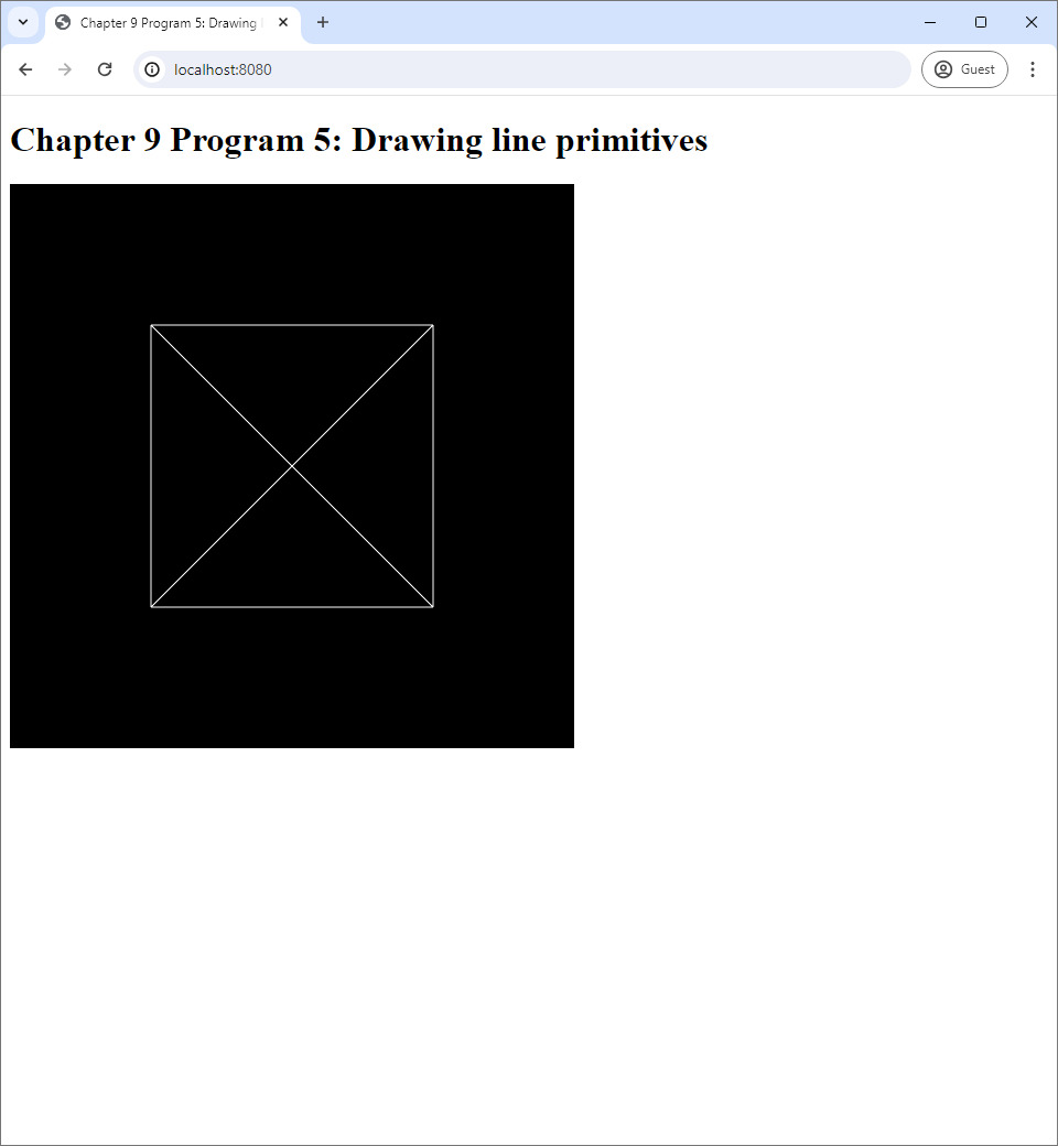
9.5 Program 5: Drawing line primitives
We have learned how to draw triangle primitives in the last three programs. Now, we turn to the remaining two primitive types: points and lines. In this program, we deal with the simpler one, the lines. Program 5 draw 6 line primitives using a vertex buffer that has 4 vertices and an index buffer. Its screenshot is given below.
The code is available in the chapter-09/program-05 directory of the book's code Github repository. Program 5's code has the same files and those of Program 4, and most files are the same except index.js. This means that we are still using the same vertex shader and fragment shader as the last three programs. We didn't change index.js much either. One change includes the values in the index buffer, which are declared in the createBuffers method of the WebGLApp class.
class WebGLApp {
  :
  :

  createBuffers() {
      let vertexData = new Float32Array([
          -0.5, -0.5, 0.0,
          0.5, -0.5, 0.0,
          0.5, 0.5, 0.0,
          -0.5, 0.5, 0.0
      ]);
      this.vertexBuffer = createVertexBuffer(this.gl, vertexData);

      let indexData = new Int32Array([
          0, 1,
          1, 2,
          2, 3,
          3, 0,
          0, 2,
          1, 3
      ]);
      this.indexBuffer = createIndexBuffer(this.gl, indexData);
  }

  :
  :
}
Notice that we are still using the same vertices that were used to draw the square in Program 3. However, the index buffer now has 12 elements because we now want to draw 6 lines, and each line is made up of 2 vertices. The index values are all 6 pairs that can be made from the numbers 0, 1, 2, and 3, and the 6 lines from these pairs would give us the 4 borders of the square and its 2 diagonals.
Another change to index.js is in the updateWebGL method. Now, we need to change how we call the drawElements method from
drawElements(self.gl, self.indexBuffer, self.gl.TRIANGLES, 6, 0);to
drawElements(self.gl, self.indexBuffer, self.gl.LINES, 12, 0);We change self.gl.TRIANGLES to self.gl.LINES because now we want to draw lines. We also need to change the number of indices to use to draw our primitives. The value is now 12 because the index buffer has exactly that many elements, and we want to use all indices.
All in all, drawing lines is pretty much the same as drawing triangles. We only need to tell WebGL to draw lines with gl.LINES enum, and we need to arrange our vertex and index buffers accordingly.
9.6 Program 6: Drawing point primitives
The only remaining primtitive to discuss is the points. While the primitive is structurally the simplest (because each point has only one vertex). From the API point of view, it is more complicated than the points and the triangles because we can manipulate the primitive more inside a vertex shader. Program 6 draws 4 points on the canvas. Its screenshot is given below.
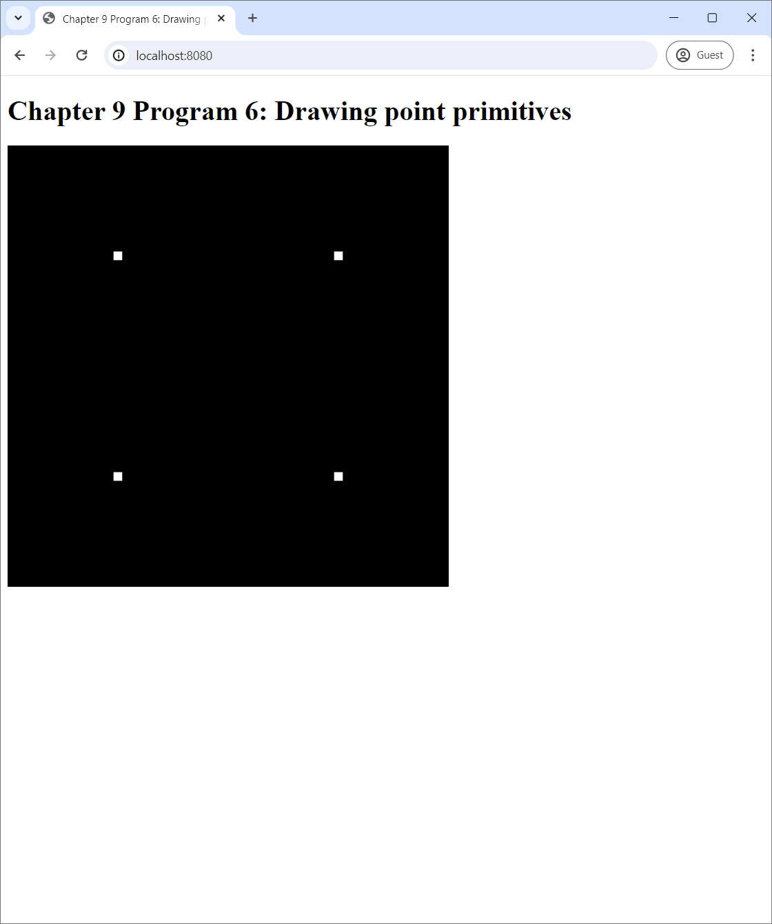
You might be surprised that what we see is 4 small squares instead of 4 points. The reason is that points in WebGL are implemented as squares, and we can control how big the square that represent a point is inside the vertex shader. Program 6's vertex shader code is stored in vertex-shader.vert like in all the other programs in this chapter, and we reproduce it below:
#version 300 es

in vec3 position;

void main() {
    gl_PointSize = 10.0;
    gl_Position = vec4(position, 1);
}
The vertex shader has one extra line:
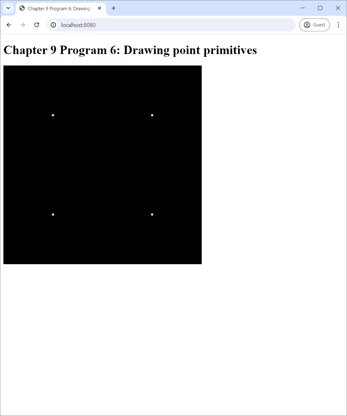
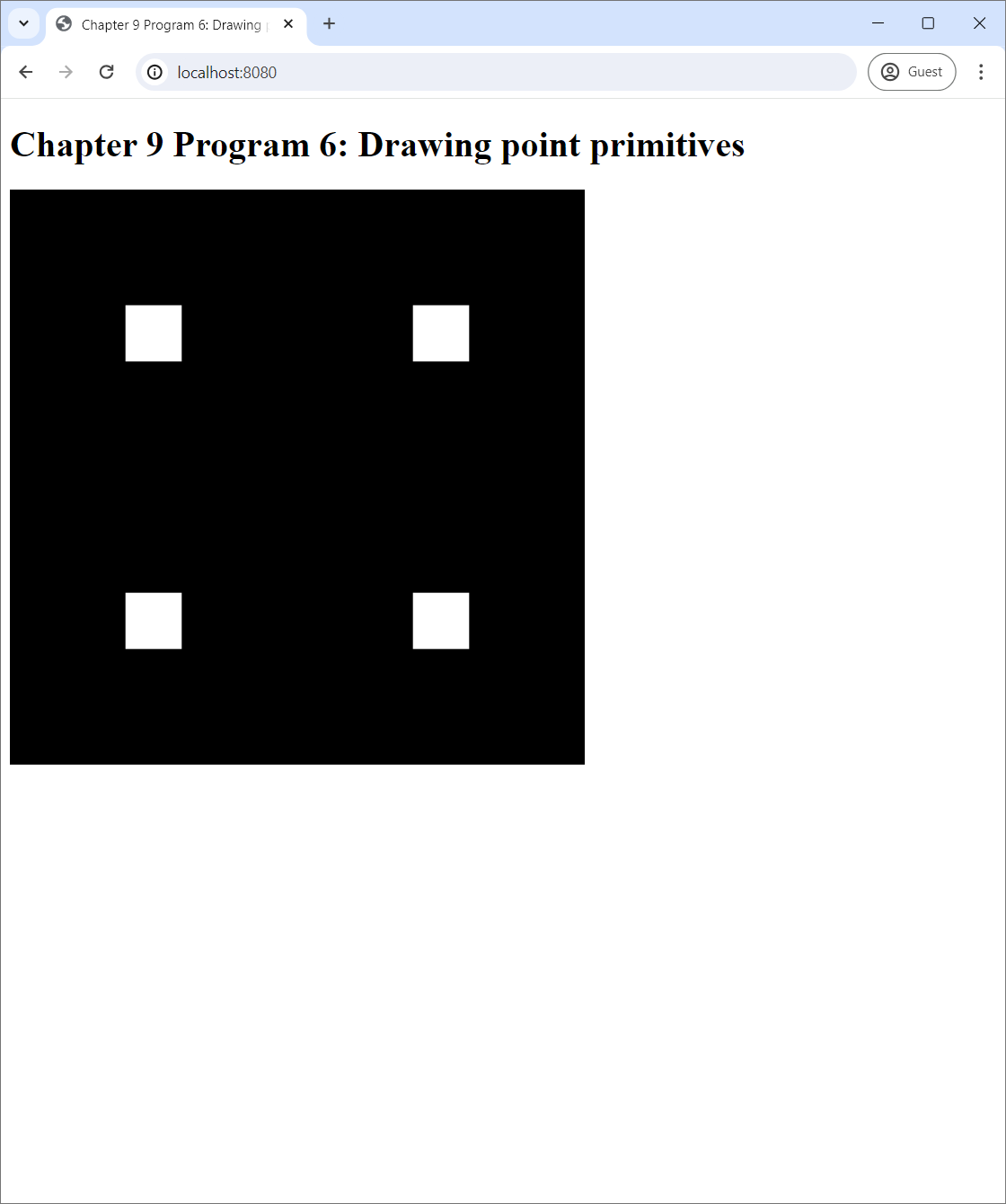
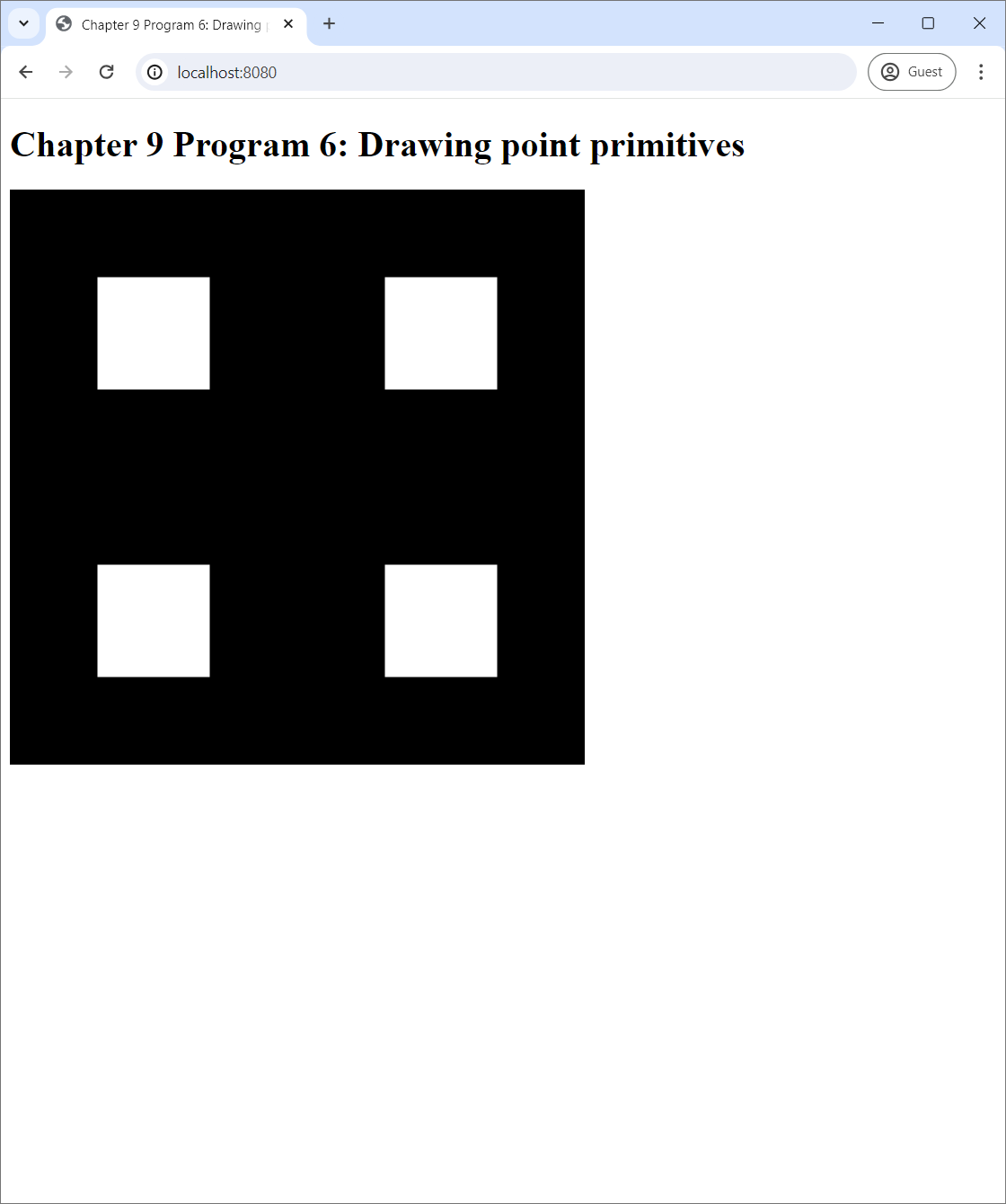
gl_PointSize = 10.0;The gl_PointSize variable stores a floating-point value the represents the size in pixels of the square that represents a point. Setting it to 10 gets us the screenshot in Figure 9.8. In Figure 9.9, we show the results of setting it to 1, 5, 50, and 100. Note that, when the point size is 1, the screen becomes completely black. As a result, we recommend that the reader sets it to at least 2.
 |
 |
| (a) | (b) |
 |
 |
| (c) | (d) |
gl_PointSize to (a) 1, (b) 5, (c) 50, and (d) 100.Program 6 has the same files as those of Program 5 with changes in only three files. The first file with changes is vertex-shader.vert, which we just discussed. The second file with changes is index.html where the web page's title was changed ("Program 5" to "Program 6"). The last file with changes is index.js.
The changes in index.js is similar to those in the last Section. First, we weed to change the index buffer.
class WebGLApp {
  :
  :

  createBuffers() {
      let vertexData = new Float32Array([
          -0.5, -0.5, 0.0,
          0.5, -0.5, 0.0,
          0.5, 0.5, 0.0,
          -0.5, 0.5, 0.0
      ]);
      this.vertexBuffer = createVertexBuffer(this.gl, vertexData);

      let indexData = new Int32Array([
          0, 1, 2, 3
      ]);
      this.indexBuffer = createIndexBuffer(this.gl, indexData);
  }

  :
  :
}
Now, the index buffer has only 4 indices instead of 12 because we want to draw 4 points, and each point has only one vertex. Second, we need to change the updateWebGL method so that it draws points instead of lines.
updateWebGL() {
  let self = this;

  this.gl.clearColor(0.0, 0.0, 0.0, 0.0);
  this.gl.clear(this.gl.COLOR_BUFFER_BIT);
  useProgram(this.gl, this.program, () => {
      setupVertexAttribute(self.gl, self.program, "position", self.vertexBuffer, 3, 3*4, 0);
      drawElements(self.gl, self.indexBuffer, self.gl.POINTS, 4, 0);
  });

  window.requestAnimationFrame(() => self.updateWebGL());
}
The only change is in the line
drawElements(self.gl, self.indexBuffer, self.gl.POINTS, 4, 0);where we change the primitive type to self.gl.POINTS and the number of vertices to 4 because we want to draw exactly four points.
In conclusion, drawing point primitives involves changing the primitive type when calling the drawElements method of the WebGL context. Moreover, we must also set the gl_PointSize to an appropriate value (which should be more than 1) in the vertex shader.
9.7 Program 7: Specifying the viewport
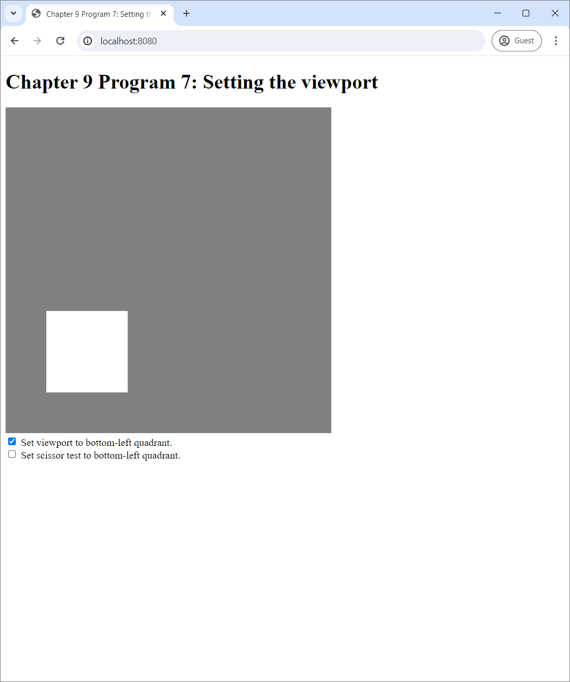
The last program in this chapter is not about drawing primitives but about setting up the viewport. A viewport is a subrectangle of the canvas in which the primitives are drawn. It is expedient to see what a viewport can do by seeing screenshots of Program 7 below.
 |
 |
| (a) | (b) |
We see that Program 7 is similar to Program 4. They both draw a single square in the middle of the screen. However, we changed the clear color of Program 7 to gray in order to distinguish between what the program does and does not do. (This will become cleaer later.) Underneath the canvas, there are two checkboxes. The first checkbox makes the program "sets the viewport to the bottom-left quadrant." If you check it, the screenshot becomes what you see in Figure 9.10(b).
9.7.1 Setting and understanding the viewport
Program 7 is Program 4 with viewport-related code added. The snippet of code that sets the viewport is in the index.js file in the updateWebGL method of the WebGLApp class. It is located after that part where we clear the screen and before the part where we render primitives. It reads:
if ($("#viewportCheckbox").is(":checked")) {
  this.gl.viewport(0, 0, 256, 256);
} else {
  this.gl.viewport(0, 0, 512, 512);
}
We can see that the viewport can be set through the viewport method of the WebGL context. It receives 4 arguments—x, y, width, and height—like the scissor method that we studied in Section 8.5. The meaning of the parametes are exactly the same. More specifically, the method sets the viewport to the rectangle specified by the 4 parameters. The coordinate system for the rectangle is such that the bottom-left corder is $(0,0)$, and the top right corner is $(W,H)$ where $W$ is the pixel width of the canvas, and $H$ is the height. See Figure 8.6 for an illustration of the semantics.
From the code snippet above, we see that, when the first checkbox in the web page is checked, the viewport is set to the rectangle $(0,0,256,256)$, which is the bottom-left quadrant of the screen. Otherwise, it is set to the rectangle $(0,0,512,512)$, which is the whole screen. This is the default viewport that all the other programs so far have been using.
The effective of setting the viewport is this: all the primitives are scaled to match the viewport's area. In Figure 9.10(a), the viewport covers the whole screen, and the white rectangle is in the middle of the screen. In Figure 9.10(b), we set viewport to the bottom-left quadrant, and so the whole screen is effectively reduced to the bottom-left quadrant. As a result, the white rectangle appears in the middle of this downsized "screen," and it becomes smaller accordingly.
It is important to remember that what the viewports affects are the primitives. It does not affect clearing of the screen. So, even after we set the viewport, the background color is still gray because the clear method of the WebGL context clears the whole screen by default. (See Section 8.3 for a review.)
7.3.2 Viewport vs scissor test
In Section 8.5, we learned about the scissor test, which is a concept quite similar to the viewport. To recap, the scissor test allows a fragment to be written to the framebuffer only if it falls inside the "scissor box" specified by the user. The scissor box is quite similar to the viewport because they both specify the area the screen where updates occur. However, they are different in two aspects.
- Primitive size. Setting the viewport changes primitive size, but the scissor test does not.
- Scope. Setting the viewport only affects primitive drawings and not clearing the screen, but the scissor test affects both.
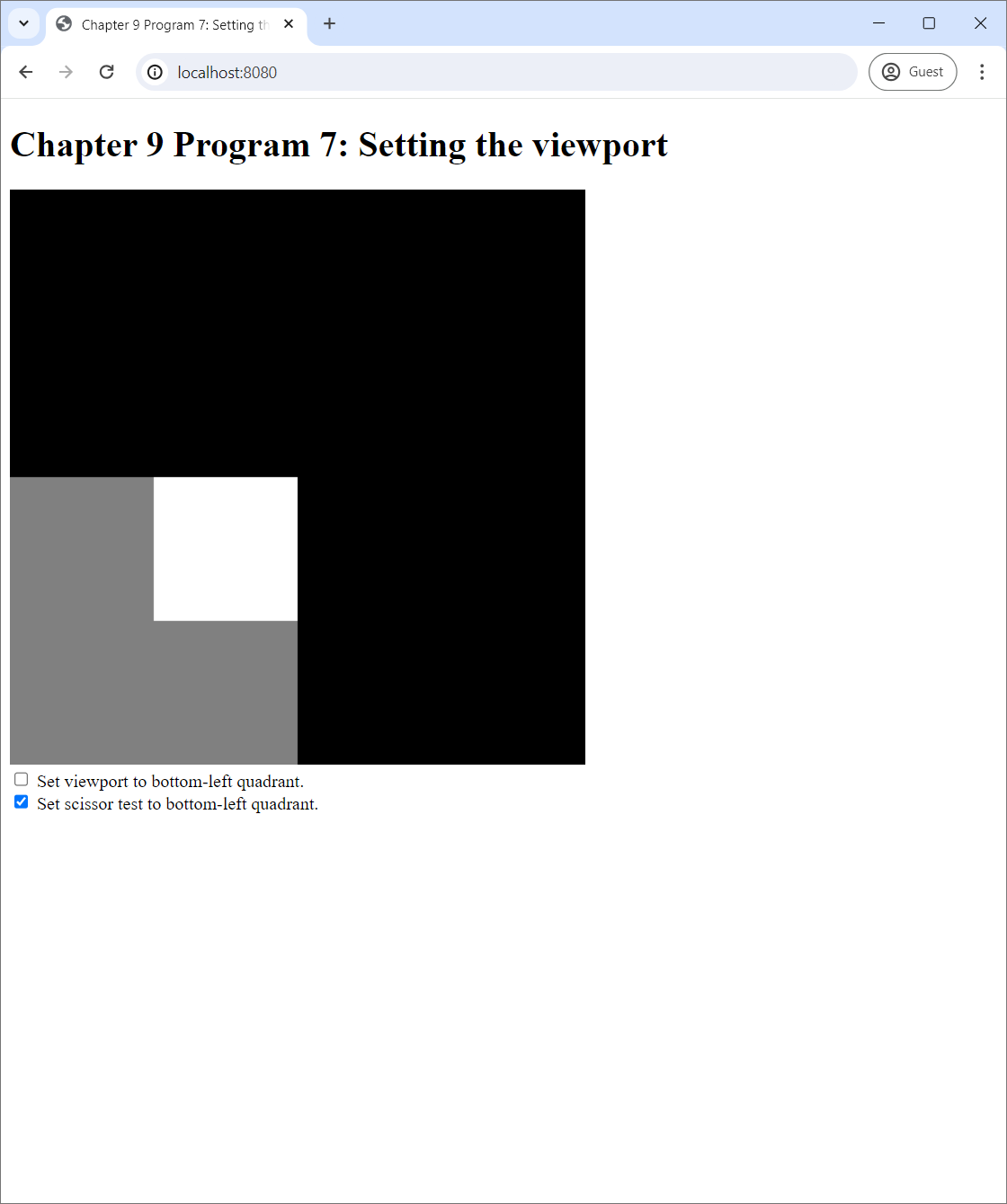
To drive the points above home, let us now use Program 7's the second checkbox, which says that the program would "set scissor test to bottom-left quadrant" when checked. The code that carries out this logic is also in the updateWebGL method, and it reads:
if ($("#scissorTestCheckbox").is(":checked")) {
  this.gl.enable(this.gl.SCISSOR_TEST);
  this.gl.scissor(0, 0, 256, 256);
} else {
  this.gl.disable(this.gl.SCISSOR_TEST);
}
The effect of checking the second checkbox is shown in Figure 9.11.
 |
 |
| (a) | (b) |
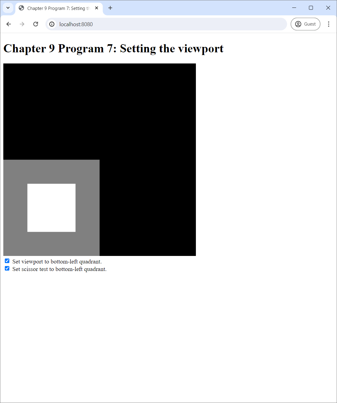
In Figure 9.11(a), we enable the scissor test but do not set the viewport. What happens is that the program is still trying to draw what we see in Figure 9.10(a), but all the fragments outside the scissor box, which is now the bottom-left quadrant, are dropped. Hence, three forths of the screen become black. The white square is still in the middle of the screen, but we only see the part of it that falls into the bottom-left quadrant. On the other hand, in Figure 9.11(b), we use both the scissor test and the viewport. The primitives are scaled down to match the smaller "screen," and the scissor test also throws out all the fragments outside the new screen. As a result, it is as if the whole screen is scaled down and pasted on the bottom-left quadrant.
9.7.3 Usage
What is the viewport and the scissor test good for? One clear use case is to use them to render multiple images on to the same screen. To do so, we partition the screen into subrectangles such that each would host one image. To render an image, we set the scissor test to throw out all fragments outside the image's subrectangle and set the viewport to the subrectangle as well. Then, we can follow the routine of clearing the screen and then rendering the primitives. This ensures that the rendering process would only affect the subrectangle we choose, and not the area outside of it. To reiterate, it is very important to use both the viewport and the scissor test when rendering multiple images on the same screen because they affect different parts of the rendering process: the viewport only affects the primitives, and the scissor test only affects the area where the fragments are written.
9.8 Summary
- We need to do multiple things to draw primitives with WebGL.
- We must to create a GLSL program.
- We must to create a vertex buffer and optionally an index buffer.
- We must then use the GLSL program and tell it how to connext the vertex buffer to the relevent vertex attribute.
- If we use an index buffer, we must also bind the index buffer before rendering.
- After all of this, we can finally issue the command to render primitives.
- After issuing the command, we need to clean up after ourselves by unbinding any boound buffers and unusing the GLSL program.
- The process of creating a GLSL program can be summarized as follows.
- Load the source code of the vertex shader and the fragment shader.
- compile source code to create the vertex shader and then fragment shader.
- Link the vertex shader and the fragment shader together to form a complete GLSL program.
- The process of creating a vertex buffer or an index buffer can be summarized as follows.
- Prepare the data and store it as a Javascript typed array such as a
Float32Arrayor aInt32Array. - Bind a buffer target. Use
gl.ARRAY_BUFFERfor a vertex buffer andgl.ELEMENT_ARRAY_BUFFERfor an index buffer. - Use the
bufferDatamethod of the WebGL context to download the data to the GPU. - Unbind the bound buffer target.
- Prepare the data and store it as a Javascript typed array such as a
- The vertex shader of a working GLSL program needs to have at least one attribute variable that would be used to receive data from a vertex buffer.
- One needs to retrieve the "location" of this attribute variable with the
getAttribLocationmethod of the WebGL context. - One also needs to connect the vertex buffer fo the attribute variable with the
vertexAttribPointermethod.
- One needs to retrieve the "location" of this attribute variable with the
- Two commands can be used to render primitives.
drawArraysis used to draw primitives with only a vertex buffer.drawElementsis used to draw primitives with a vertex buffer and an index buffer.
GLEnum. The primitives we cover in this chapter are:gl.TRIANGLESgl.LINESgl.POINTS
- When rendrering point primitives, one must set the
gl_PointSizevariable inside the vertex shader.- It is advisable to set it to a floating point value greater than 1.
- The viewport is a subrectagle of the screen where primitives are scaled to conform with its extent.
- It can be set through the
viewportmethod of the WebGL context. - The viewport, when used together with the scissor test, is useful for drawing multiple images on to the same screen.
- It can be set through the